“[Finally] getting some rock delivered now, though we are still behind schedule.  Quite a weekend here, no work on Friday – but Saturday and Sunday very productive (in terms of placing rock for Newbury Riffle).  Punctuated by huge afternoon thunder storms.  Must have rained at least 6 inches in an hour this afternoon!!
We are about 1/3 complete, you can see if look carefully the riffle toe downstream and the crest now built upstream.  The crest and middle of weir will come up about another meter.
I’m teaching a course for area engineers on Tuesday morning, then a field trip out to the site.  Wedensday morning will be my last day as I fly out from KL on Thursday.  
In meantime Ill layout everything conceivable to guys and they can finish without me.”
Ciao!
-John


>


Here’s another EXCLUSIVE update straight from John McCullah himself in Malaysia-

“Update from project

Sg. Pedu site is 9km below huge Pedu Dam. The reservoir touches Thai border.

The toe of Newbury Riffle is in, but the Rock Delivery is still too SLOW.

We Need to lay 500T per day, only getting 200 T per day.  So we are way behind schedule.

 The riffle has well graded stone (30” – 2”) well compressed.  It will be over 120’ long riffle with crest 2 meters (6ft high) then we plans on one Bendway Weir upstream to direct flood flows onto Riffle.  This river can get 125,000 cfs in winter !!!   No wonder gabion check dam failed

Wing Leong and I have been there everyday!!!”


Looks like a lot of work, but a lot of fun as well! We will be in contact with John throughout most of his trip, and we will keep you updated as the project builds!

Don’t forget to subscribe to our site for messages for current news, events, and projects!

Thanks for reading!

– The Dirt Time Team


Hello! This just in from the other side of the GLOBE!!!

John is in Malaysia with Wing where they are working on and Engineered Newbury Riffle and the first Bendway Weirs in that part of the world.

John says the first few day were filled with construction logistics – getting equipment lined up and visiting local quarries to get the right rock.

The project is about 30 km below a large dam near the border with Thailand.  The purpose for the work is to raise the water elevation so a large series of pumps can utilize the river water for irrigation of farms and rubber tree plantations.  

First thing was to dismantle an old gabion check dam that had been built to serve that purpose – unfortunately the river had “blown out” around the check dam.

Check out the HOT OFF THE PRESS PICS!!

More on the design and construction later.  


PROJECT: OPAL CLIFFS


PROJECT TYPE: Bluff Repair
and Stabilization


PROJECT SCALE: Small


CLIENT/OWNER: Local Homeowner


TECHNIQUES EMPLOYED: Anchored
TRM, Live Staking, Hydroseeding


GEOGRAPHIC LOCATION: Opal Cliffs
Drive, Santa Cruz, CA 


GEOMORPHIC SETTING:   Sea cliff subject to active erosion and periodic retreat.  The Opal Cliffs-Capitola reach is characterized by an irregular shoreline backed by cliffs ranging from 35 to 75 feet in height.  The coastal cliffs throughout most of the city of Santa Cruz and neighboring Capitola are composed of erodible sediments of the Purisma Formation (siltstone and sandstone) along with the Santa Cruz Mudstone.  These sedimentary rocks are often capped by 6 to 20 feet of unconsolidated marine and non-marine terrace deposits.  The horizon-tal bedrock stratigraphy is easily visible in exposed or bare sections of the cliffs.

SITE CONDITIONS AND PROBLEMS: The Opal Cliffs section of the coastline is at high risk from erosion, the narrow beaches provide little protection from wave attack at the base of the cliff.  Urbanization and house building at the cliff top causes further sub-aerial erosion threats, viz., concentrated runoff and subsurface seepage from streets, drains, downspouts, and excessive lawn watering.  The face of the cliff at the location of the residence was actively eroding and retreating (see Fig. 20.1).

Figure 20.1 – Coastal bluff before treatment


TREATMENT OBJECTIVES AND CONSIDERATIONS: As a result of the high erosion risk from wave attack large sections of the sea cliff are protected by struc-tures including sea walls and rock revetments.  The base of the cliff at this location is protected by a sea wall and rock armor.  The main problem appeared to be erosion and shallow sloughing at the face of the bluff.  The goal was to arrest this erosion and stabilize the face.  Adjacent stable sections of the cliff were well vegetated.  If the face of the bluff was stabilized sufficiently this would allow the establishment of vegetation which in turn would help control erosion problems.  There was insufficient evidence of emergent seepage at the bluff face to warrant installation of horizontal drains (hydraugers) on the bluff face or a trench interceptor drain atop the bluff. 


TREATMENTS SELECTED:

  •  Anchored TRM: A three-dimensional, turf reinforcement mat (TRM) was draped over the cliff face and anchored (nailed) to the slope by driving pins with large washers through the TRM into the slope (see Fig. 20.2).  Workers rappelled down the bluff face on ropes to drive the pins.  Two-foot long anchor pins were inserted on 3-foot centers (see Fig. 20.3).


  • Live Stakes: Once the TRM was securely fastened to the slope, live willow stakes were inserted through the mat into the slope (see Fig. 20.4).  The near vertical inclination of the cliff face required that this installation be done by workers suspended by a rope and sling system from the top of the bluff.
  • Hydroseeding: A specially designed mixture was sprayed on to and through the turf reinforcement mat by workers suspended on ropes from the top using hand held spray nozzles (see Fig. 20.5).  The mixture consisted of Flexterra @ 4000#/ac, native grass seeds (Maritime mix), Jumpstart (Profile) humic acid, and BioPrime (Profile) mychorrizae.

OBSTACLES TO IMPLEMENTATION: The main obstacle to implementation was the need to work on a near-vertical slope which required the use of ropes and slings.  A system was quickly developed, however, that overcame this challenge without the need for an elaborate scaffolding or support system.

PERFORMANCE EVALUATION: A vegetative cover was soon established that was initially held in place by the anchored TRM.  This provided enough time for the live stakes to root and gain a toe-hold on the steep slope.  Erosion and shallow sloughing on the face has been arrested (see Fig 20.6).  Only time will tell whether this treatment will suffice in the long run, or whether other measures such horizontal drains and/or an interceptor trench drain will be required.

Figure 20.6 – Views of bluff site immediately after treatment


BENEFITS AND LESSONS LEARNED:


  1. Bio-stabilization measures can be used effectively to repair and stabilize the face of coastal bluffs. Special anchoring provisions may be required when attaching a TRM to a near vertical slope face.
  2. The combination of an anchored TRM and live staking were used in conjunction with a site adapted hydroseeding mix to stabilize a bluff face.


REFERENCES:

Brabb, E. (1997).  Geologic Map of Santa Cruz County.  US Geological Survey, Menlo Park, CA


 This is another great chapter out of Bioengineering Case Studies . Please see to the previous link for information on ordering your today!

Thanks for Reading!!!

– The Dirt Time Team


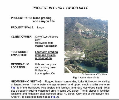
PROJECT #20 – LOWER SULPHUR CREEK

PROJECT TYPE:  Salmonid Stream Restoration

PROJECT SCALE:  Moderate, approx 1 mile of stream realignment and habitat restoration.

CLIENT/OWNER: Sacramento Watershed Action Group (SWAG) and Co-ord Resource Management Group 

TECHNIQUES EMPLOYED:

— Willow & Cottonwood Pole Planting
— LWD & Rock Habitat Structures
— Newbury Rock Riffle
— Rock Vanes
— Stream Realignment

GEOGRAPHIC LOCATION: Turtle Bay / Redding Arboretum, North Redding, CA

GEOMORPHIC SETTING: Sulphur Creek is a small, seasonal tributary stream to the Sacramento River. The watershed comprises approximately 3,000-ac with 7-mile stream length. The Sulphur Creek Watershed Analysis and Action Plan (SCWAAP), 1996, documented that the lower 2 miles of Creek can provide valuable salmonid spawning and rearing habitat if stream form and function can be restored.

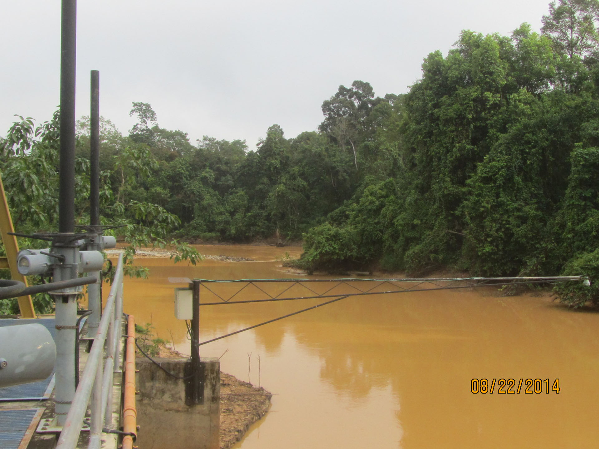
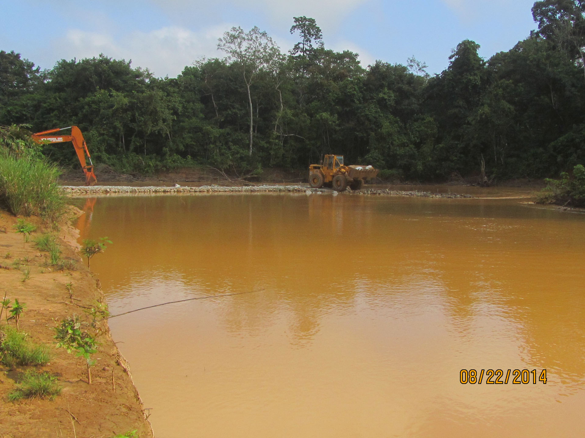
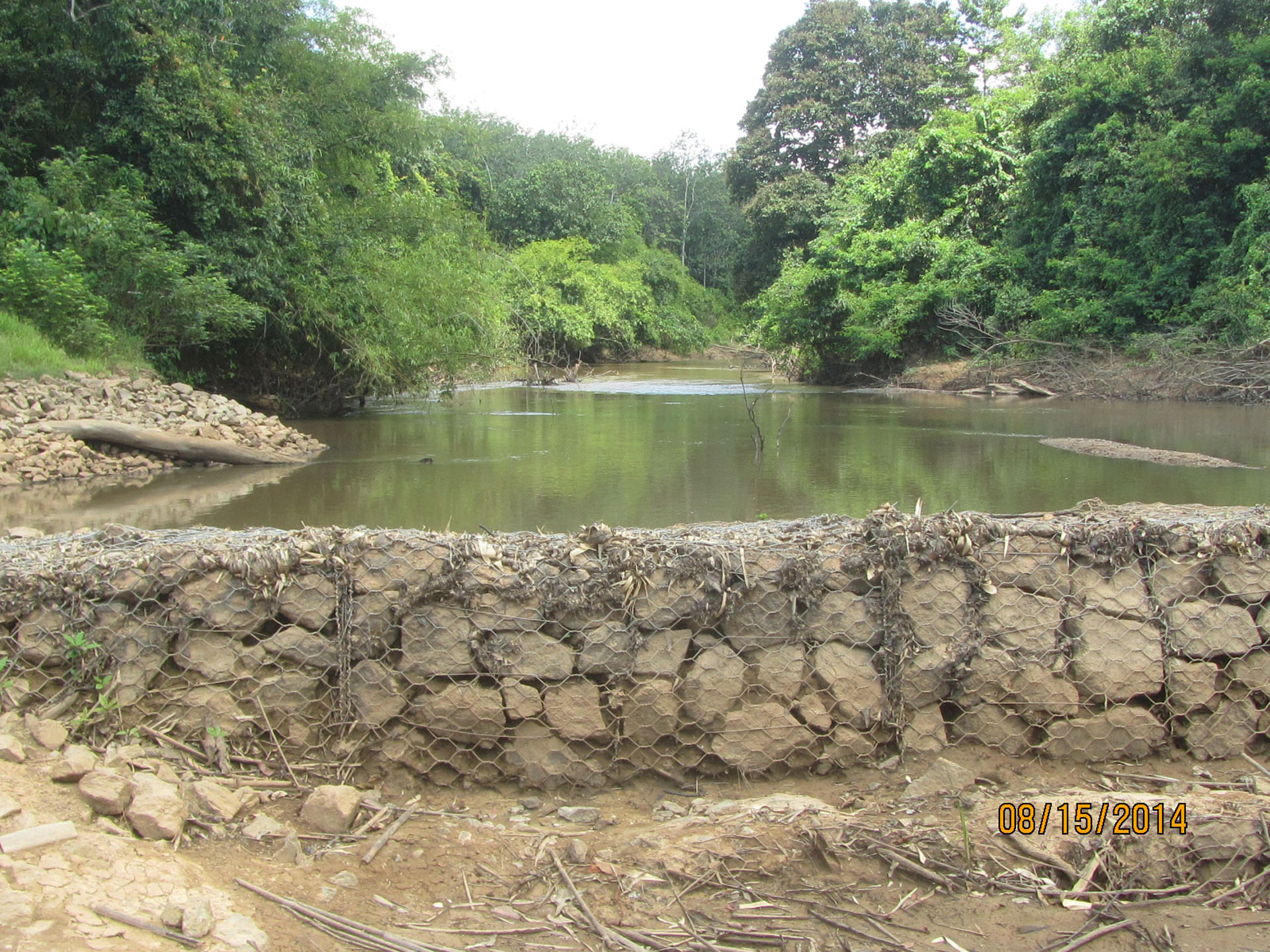
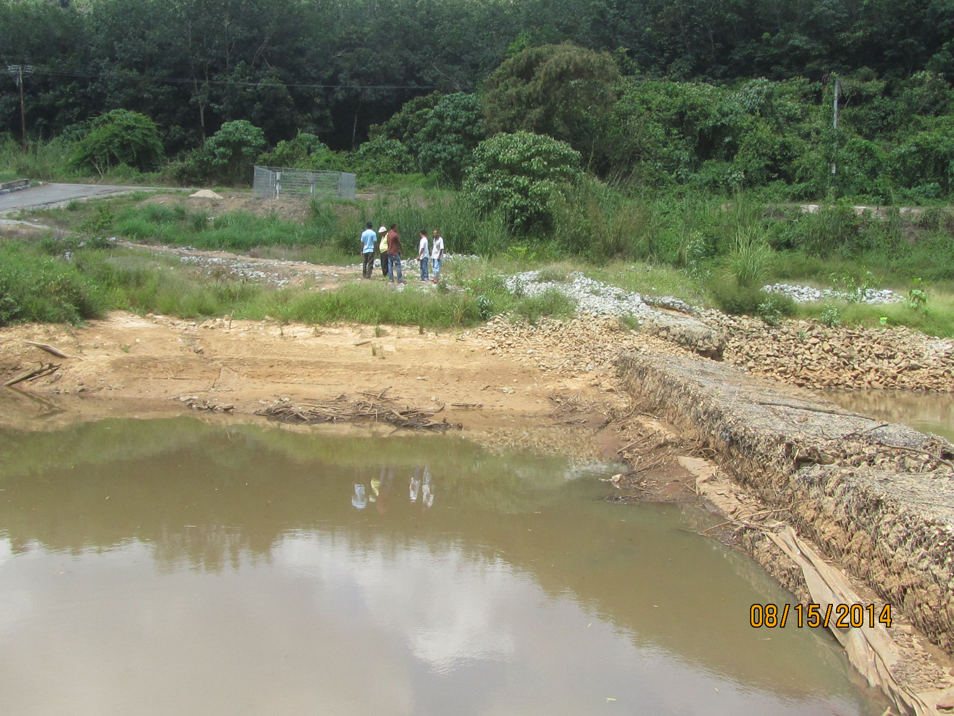
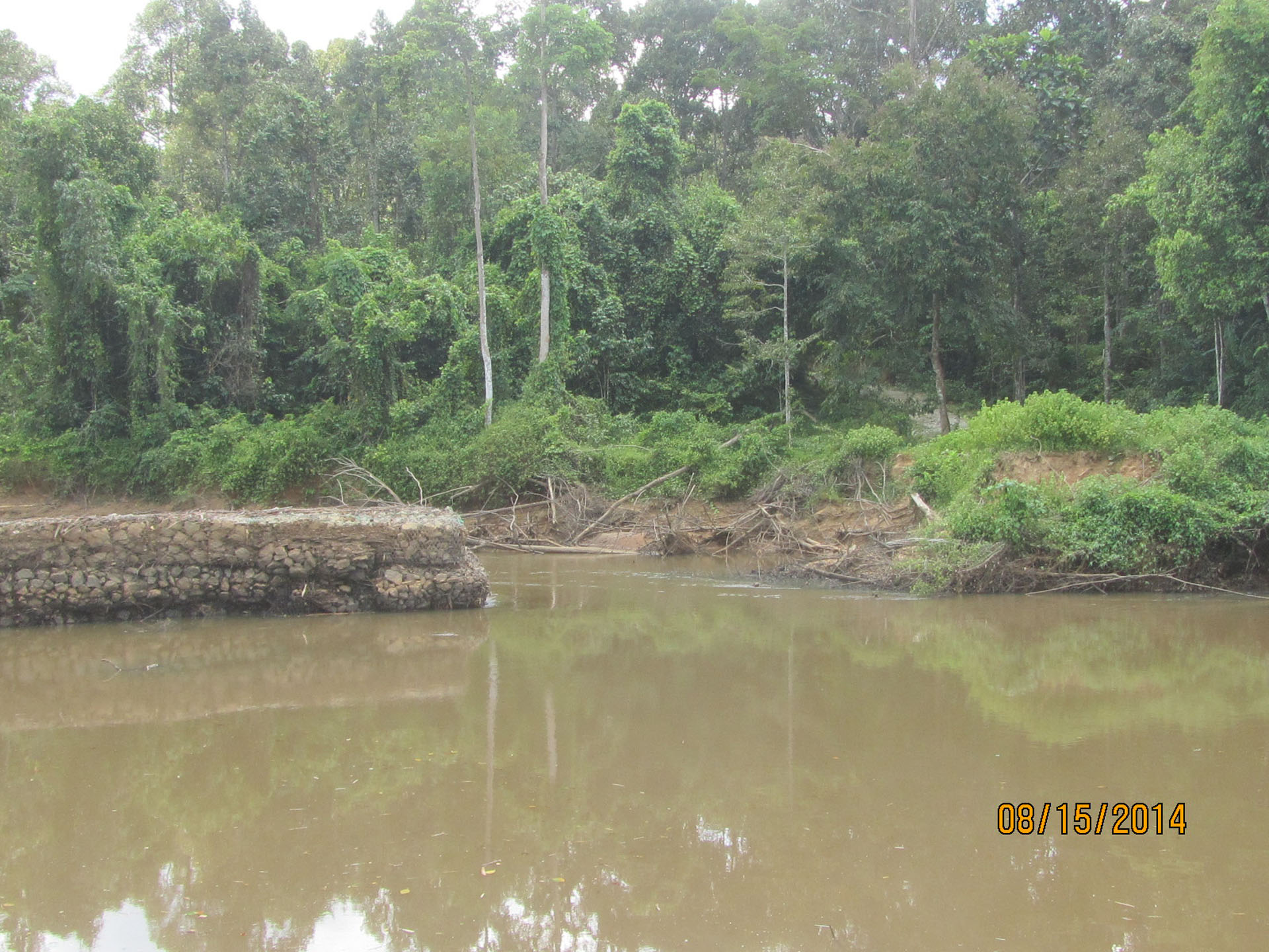
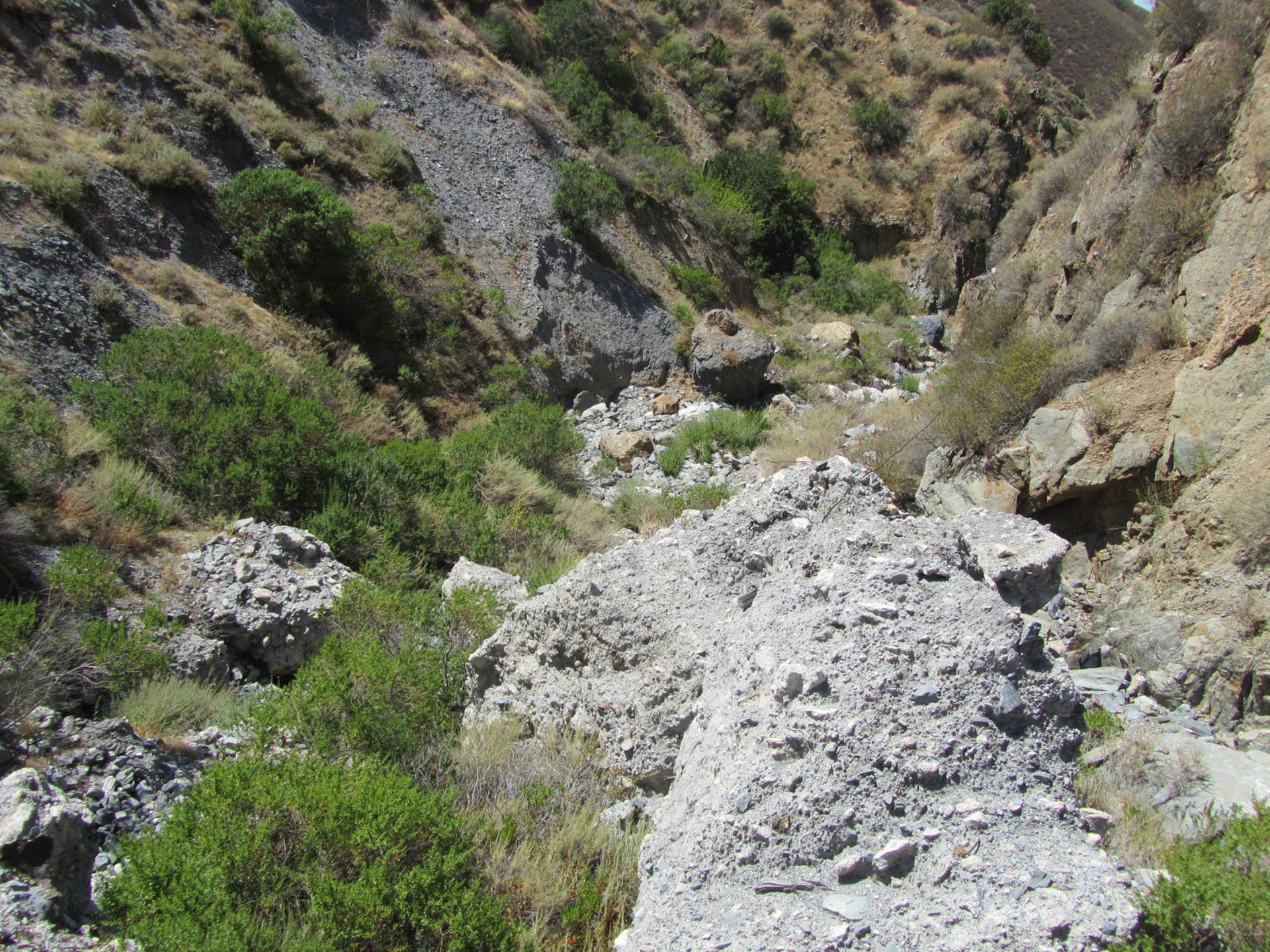
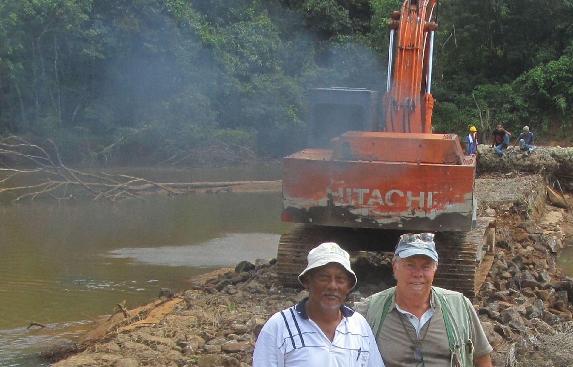
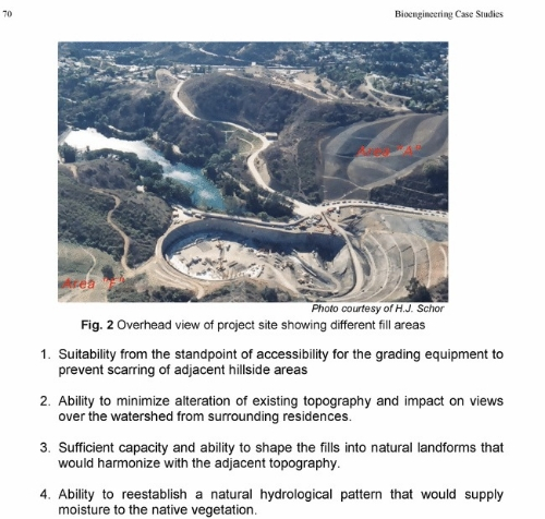
SITE CONDITIONS PROBLEMS: The entire watershed, especially the in-stream sections, has been AND severely impacted by hydraulic mining and dredger mining in circa 1800’s and gravel mining and road/highway building in the early-mid 1900s (see Figure 20.1) Lower Sulphur Creek (approximately 1 mile) runs through the Redding Arboretum.  This section had been dredged for gold (circa 1850s and 1920s) and some of the dredger piles had been subsequently mined for gravel (circa 1930-1950) thereby removing the gravel-sized substrate from the stream system and leaving cobble- and small boulder-sized piles of rock in the stream and flood plain.  A very significant land use impact occurred in 1934 when Highway 273 was build.  The new box culvert diverted the stream out of its’ historic channel and into the adjoining oak/savannah woodland.

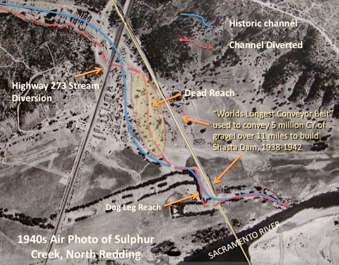
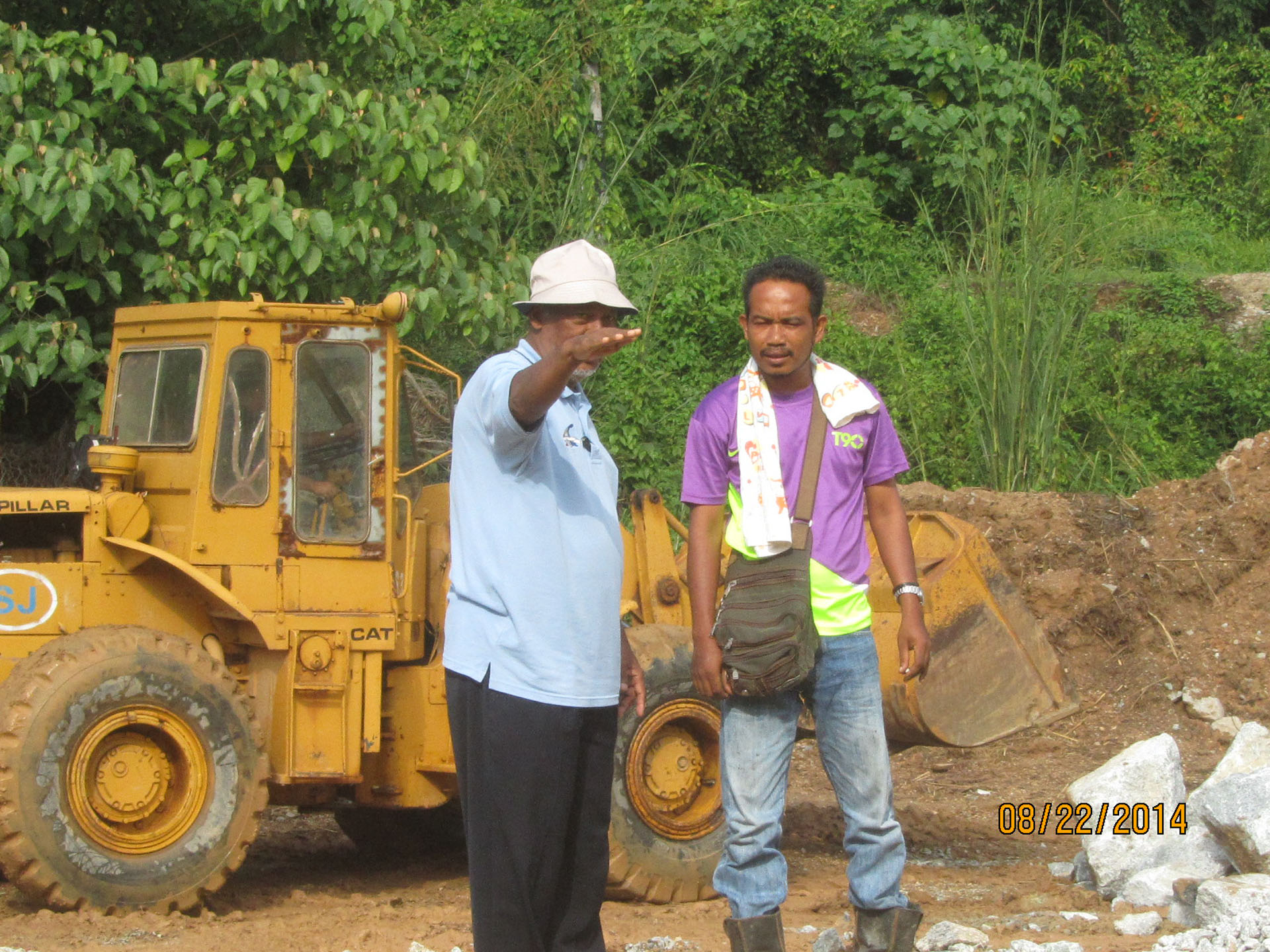
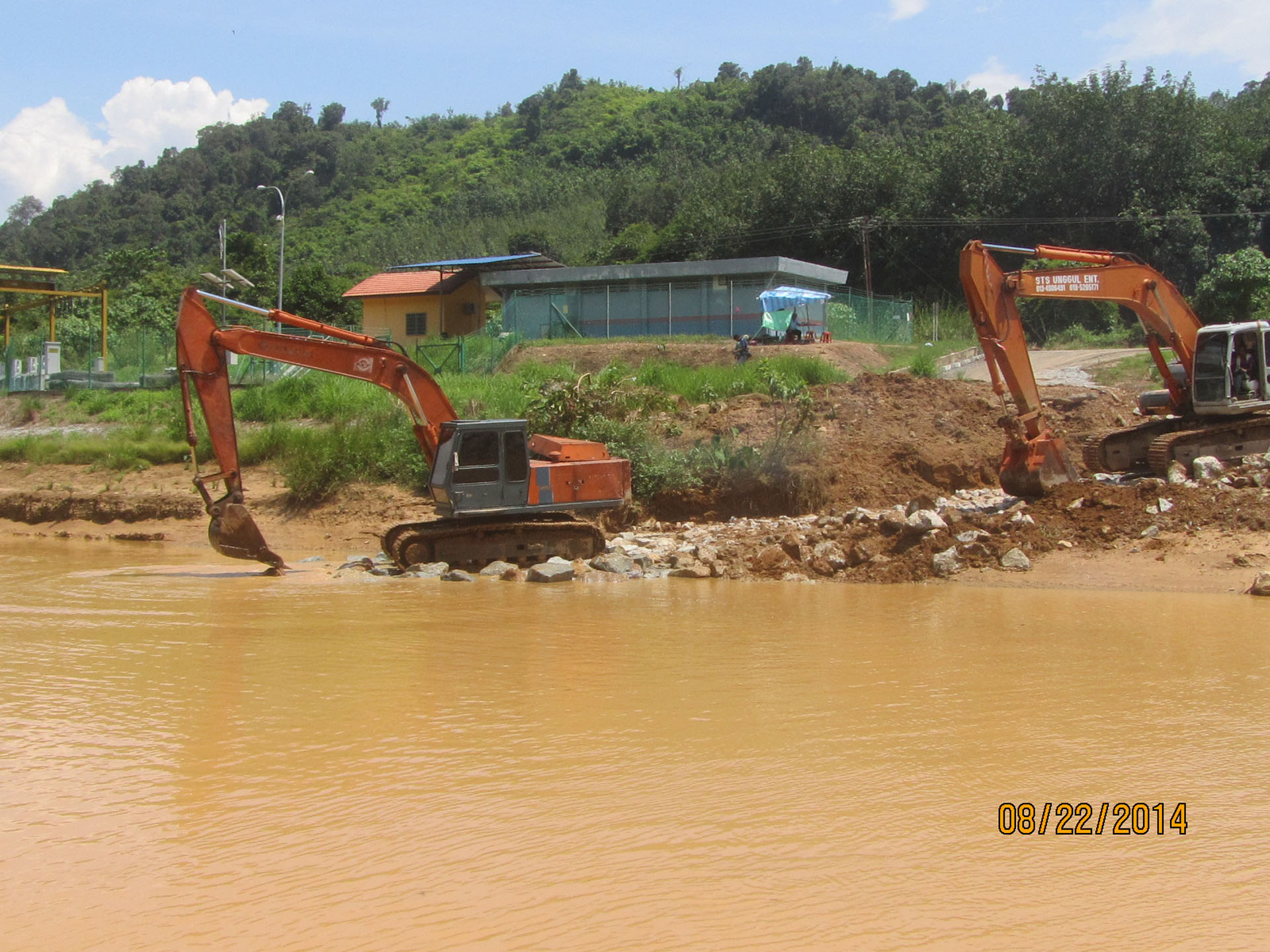
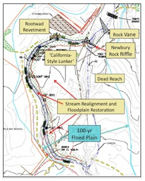
Figure 20.1 – Site Conditions in the Lower Sulfur Creek Watershed


TREATMENT OBJECTIVES AND CONSIDERATIONS:

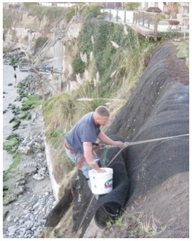
Prior to restoration the stream in this reach is severely aggraded.  The stream gradient in this lower reach is very low – an ancient alluvial fan – therefore the streams ability to transport sediment and bedload is low.  The historic land uses have exacerbated this problem because the stream has been diverted out of its original channel by the upstream highway box culvert and it has been diverted around and through the gravel mining tailings.  Early gold mining “turned the channel upside-down” then gravel mining in the mid 1900s removed the gravel-sized alluvium.  Subsequently, the creek was diverted into  modified dredger areas.  In summary, the pre-restoration condition was characterized by a channel with a convex-up stream bottom, choked with large cobble, severe bank erosion, and little to no bank vegetation.  One 1000-ft section of the stream was nicknamed “the dead reach” for all the young escaping salmonid frye that died as the stream dried up (went subsurface) episodically (see Figure 20.2). 

The primary objective for improving stream function was to re-align and mimic it’s historic plan form while excavating the excess bedload material.  The secondary goal was to increase instream and riparian habitat.  The plan for fisheries improvement was threefold:

  1. remove obstacles to anadramous fish migration and improve spawning habitat,
  2. provide rearing habitat,
  3. improve late Spring flows to allow ‘fish escapement’.

Simultaneously, the SWAAP designated and prioritized watershed-wide projects intended to reduce erosion and sedimentation.  The entire Sulphur Creek Restoration effort implemented by Sacramento Watersheds Action Group (SWAG) was conducted over an 11-year period, 1996 – 2007.

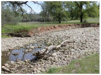
Figure 20.2 – The “Dead Reach” in Lower Sulphur Creek

TREATMENTS SELECTED:

  •  Stream Realignment and Floodplain Restoration: In 2002 SWAG and the Sulphur Creek CCRMP received a $160,000 grant from Cantara Council to design, permit, and re-align approximately 2,000 feet of stream. A new low flow channel was excavated to divert Sulphur Creek back into it’s historic channel. The historic stream dimensions, e.g., Bank Full width, slope, and sinuosity, as determined from a ‘reference reach,’ were used to guide design and implementation. The inner bend(s) of the re-aligned reach were excavated to allow floodwaters to access the floodplain.
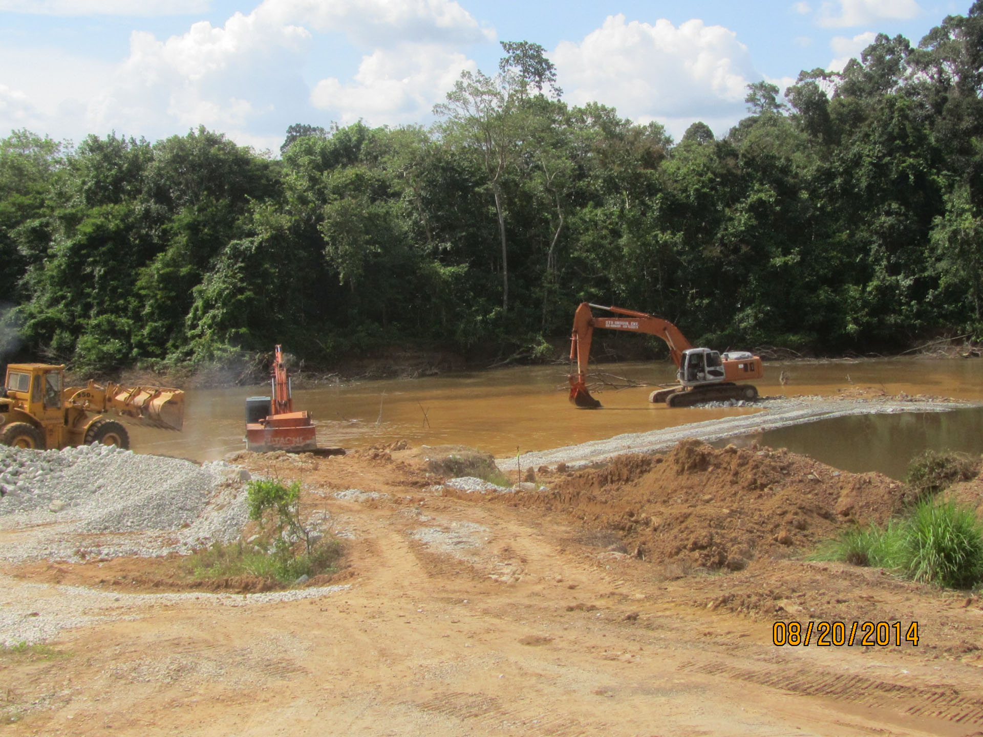
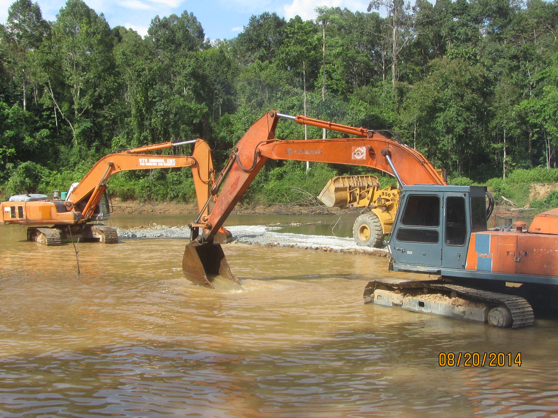
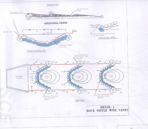
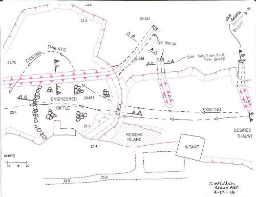
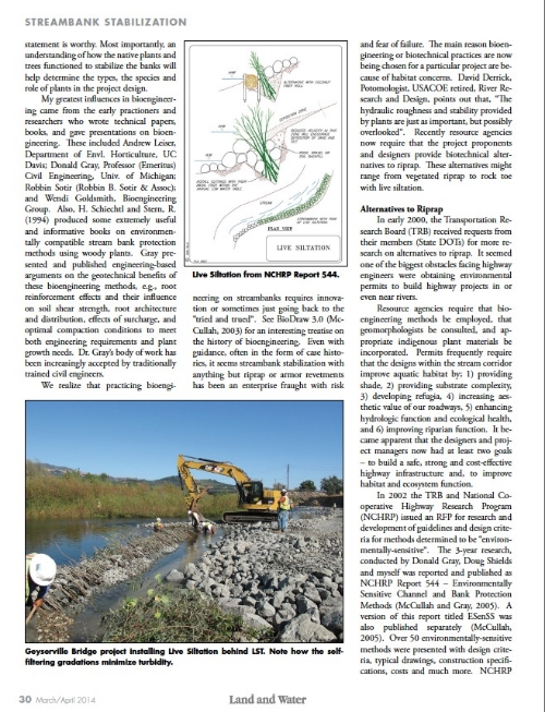
  •  Newbury Rock Riffle: In order to reduce the risk of flooding in the re-aligned reach, and ensure the stream had a sustained low flow for fish escapement, a split-flow was desired at the upstream diversion.  Flood stage was determined at about 3000 cfs and at approximately 500 cfs the stream was designed to flow into both the degraded reach and the new re-aligned reach.  The split flow was achieved with a rock weir designed as a Newbury Rock Riffle. The riffle crest was built one-foot higher than the bottom of the low flow re-aligned channel (see Figure 20.3).

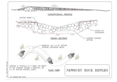
Figure 20.3 – Schematic diagram of Newbury Rock Riffle

  • Large Woody Debris (LWD) and Rock Structures: The re-aligned reach had LWD structures constructed at strategic places along the outer bends – primarily locations anticipated to receive impinging flows – thus fostering the development of scour / resting pools.  The structures were constructed of large wood (rootwads), large rock, and anchored with deeply planted willow and cottonwood poles (see Figure 20.4).

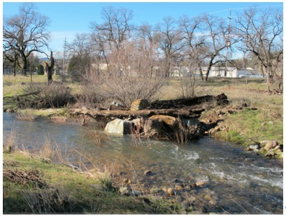
Figure 20.4 – LWD structured constructed from logs/rootwads, boulders,
and pole plantings for vegetative anchoring.


  •  Rock Vane: A Rock Vane was built approximately 300 ft upstream of the re-alignment project.  The vane was intended to protect a mature oak tree and begin to “re-direct” the stream flow into the re-aligned reach.  This vane, built in 2003, was the first rock vane designed and built by the author.  It has been thoroughly monitored and photographed over the last 10 years.  The oak tree subsequently burned down during a wildfire, however the rock vane continues re-direct flows away from the exposed bank while promoting in-stream habitat (see Fig. 20.5).
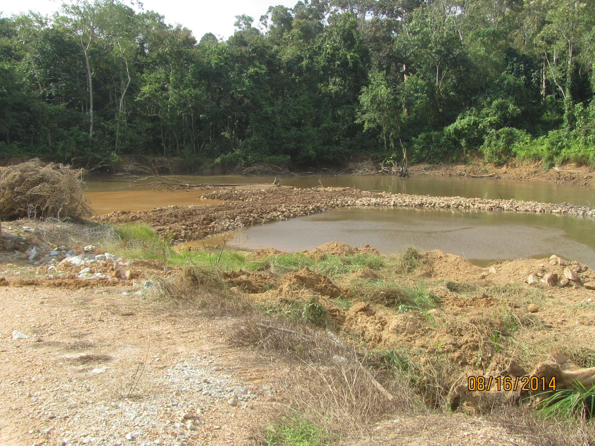
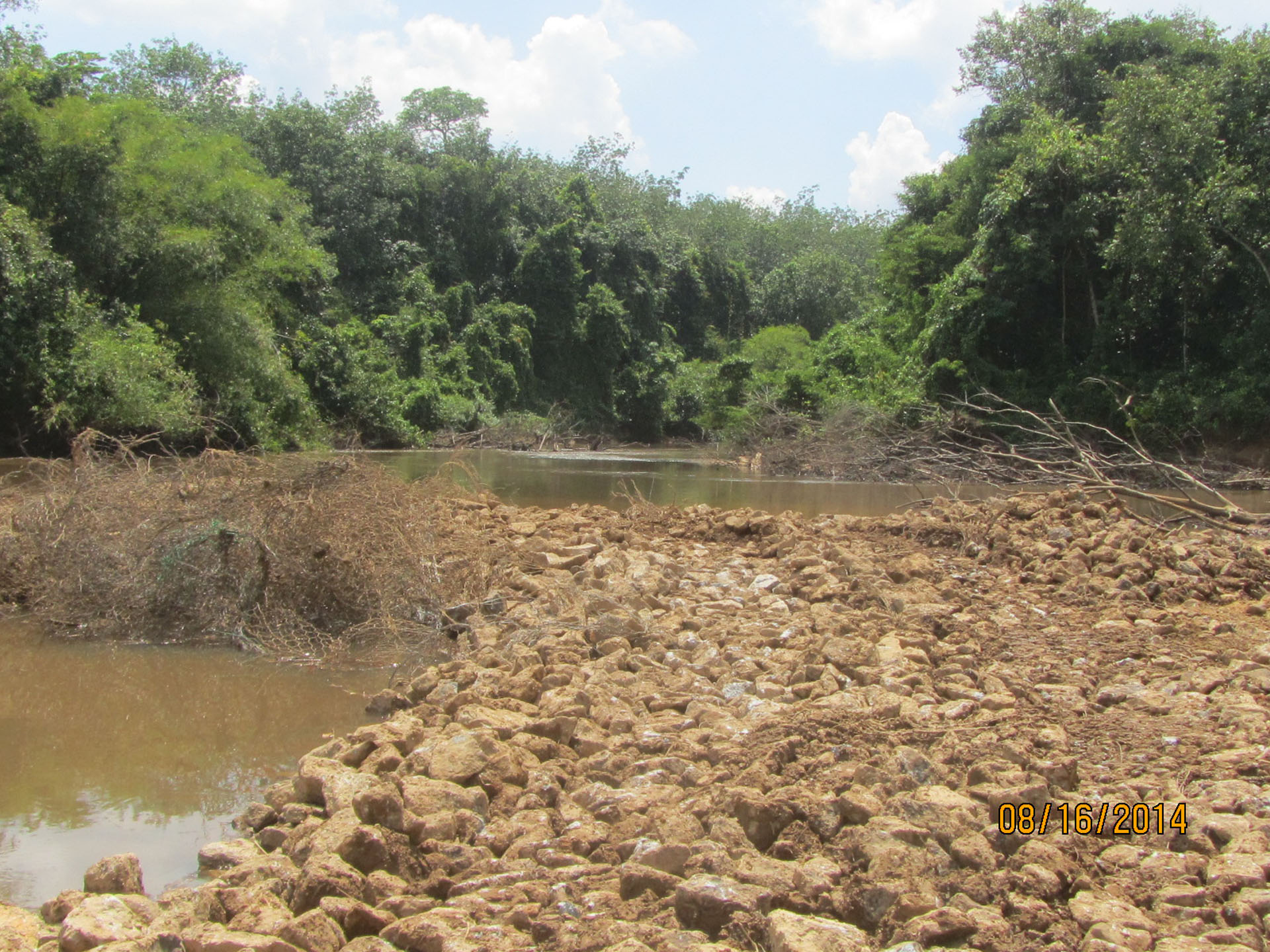
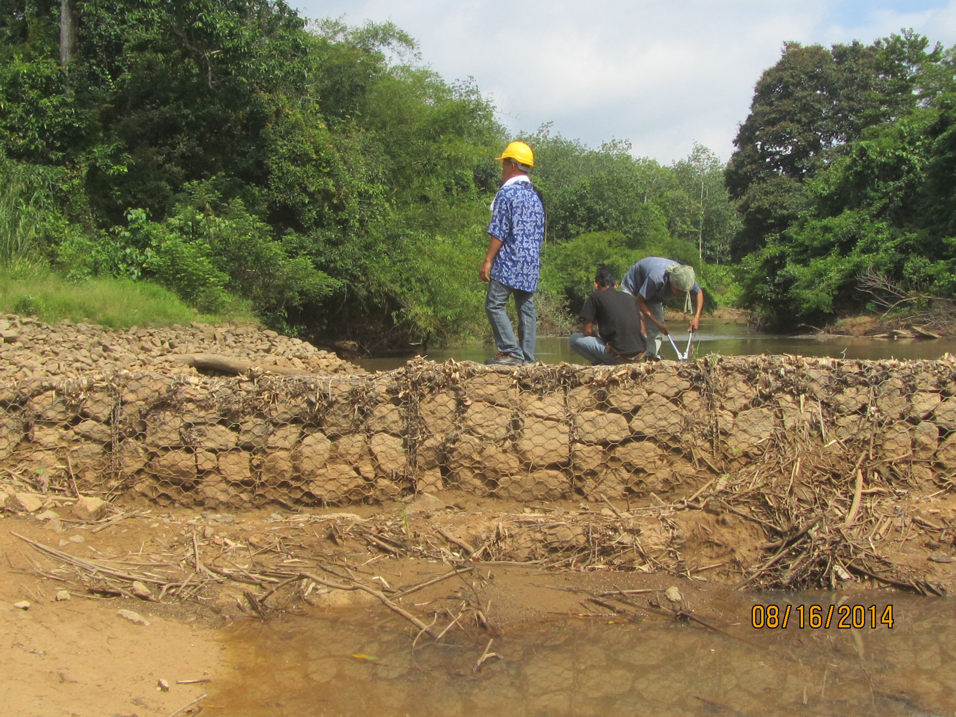
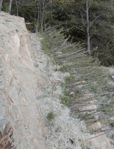
  • Longitudinal Peaked Stone Toe with Live Siltation: Longitudinal Peaked Stone Toe (LPSTP) are generally built low.  The willow branches of Live Siltationare arrayed in such a way to provide local roughness.  LPSTP with Live Siltation can not only arrest outer bank erosion, but often lead to deposition in those areas.  By September 23, 2003, the restoration effort had run out of grant money and time (the NPDES/CaDFG Permits allowed work until October only). Since there were insufficient funds or time to “layback” the tailings along the outer bend, an alternative construction technique was employed.  The outer bend material was excavated nearly vertical. Then a rock toe about 3-ft high (designed to a height near average annual or bankfull elevation) was built longitudinally along the bend (see Figure 20.6).  Before the vertical cut could collapse, willow branches (Live Siltation) were quickly and carefully placed behind the rock.  The branches were 6-9 ft long to insure they were placed as deep as possible for establishment.  Earthen debris and tailings from the vertical cut were then raked down to backfill behind the LPSTP and around the willow (see Figure 20.7).

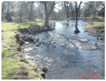
Figure 20.5 – Rock Vane built at beginning of project reach – to protect
Oak tree on left decending bank and to direct flows toward Newbury riffle
and restored reach.

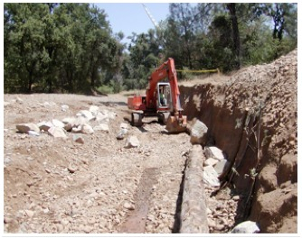
Figure 20.6 – Dogleg excavation looking downstream. Outer bend
is nearly vertical; rock and log toe are being placed in preparation
for “Live Siltation.”

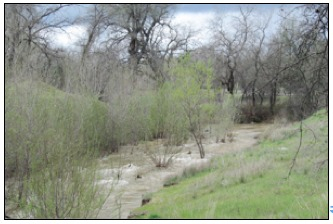
Figure 20.7 – Dogleg rock toe and “Live Siltation” seven years after construction.


OBSTACLES TO IMPLEMENTATION:

The biggest obstacle to this project was the permitting process. The CEQA rules and guidelines were applied to this project as if it was a development instead of a self-mitigating restoration.  All parties, the City of Redding and SWAG were inexperienced, therefore it took about 2 years and almost ½ of the restoration / implementation budget to permit the project.  Eventually SWAG had to complete City / FEMA Flood Map revisions even though the restoration involved removing tons of gravel tailings from the floodplain.

Urban stream restoration activities seem to make regional flood planners nervous – unfortunately many commonly-used tools such as HEC-RAS do not accurately reflect the impacts of localized activities such as willow planting, rootwad / large woody material placement, or redirective methods such as rock vanes.  HEC-RAS assumes that the channel bottom is essentially “fixed” while the restorationist wants scour pools, riffles etc.  The localized scour and low flow incisions quite often compensate for placing some material in the floodplain.

Secondarily, State and Federal laws, which are interpreted and enforced by inexperienced regulators, is extremely problematic.  For example, at one time a State Water Quality regulator advised the project supervisor to put silt fences in the stream and to line the channel bottom with erosion control mats.  The regulator apparently failed to understand the nature of restoring aquatic and salmonid habitat.  Future stream restoration projects which were regulated by State and Federal Agency staff familiar with, and supportive of, restoration activities went much smoother and resulted in maximum ecosystem benefits.


PERFORMANCE EVALUATION

The Lower Sulfur Creek project is relatively complex and required careful co-ordination among its different elements and components.  The system performed well during and after intense rainstorms and high velocity stream flows following construction.  In spite of several instances of high water the protective structures and vegetation stayed in place and displaced erosive, high velocity flows away from the stream bank while preventing further erosion of the stream bank.  Low flows are now diverted to the restored channel by a Newbury Rock Riffle on left diverts low flows to restored channel (see Figure 20.8)..  Vegetation established well both atop the flood terrace and near the water’s edge.  Channel degradation appears to have been arrested and sediment is being flushed through the creek to the Sacramento River.  The salmonid fish habitat has been restored and frye are no longer trapped during low flows which are now diverted to the restored channel.


BENEFITS AND LESSONS LEARNED

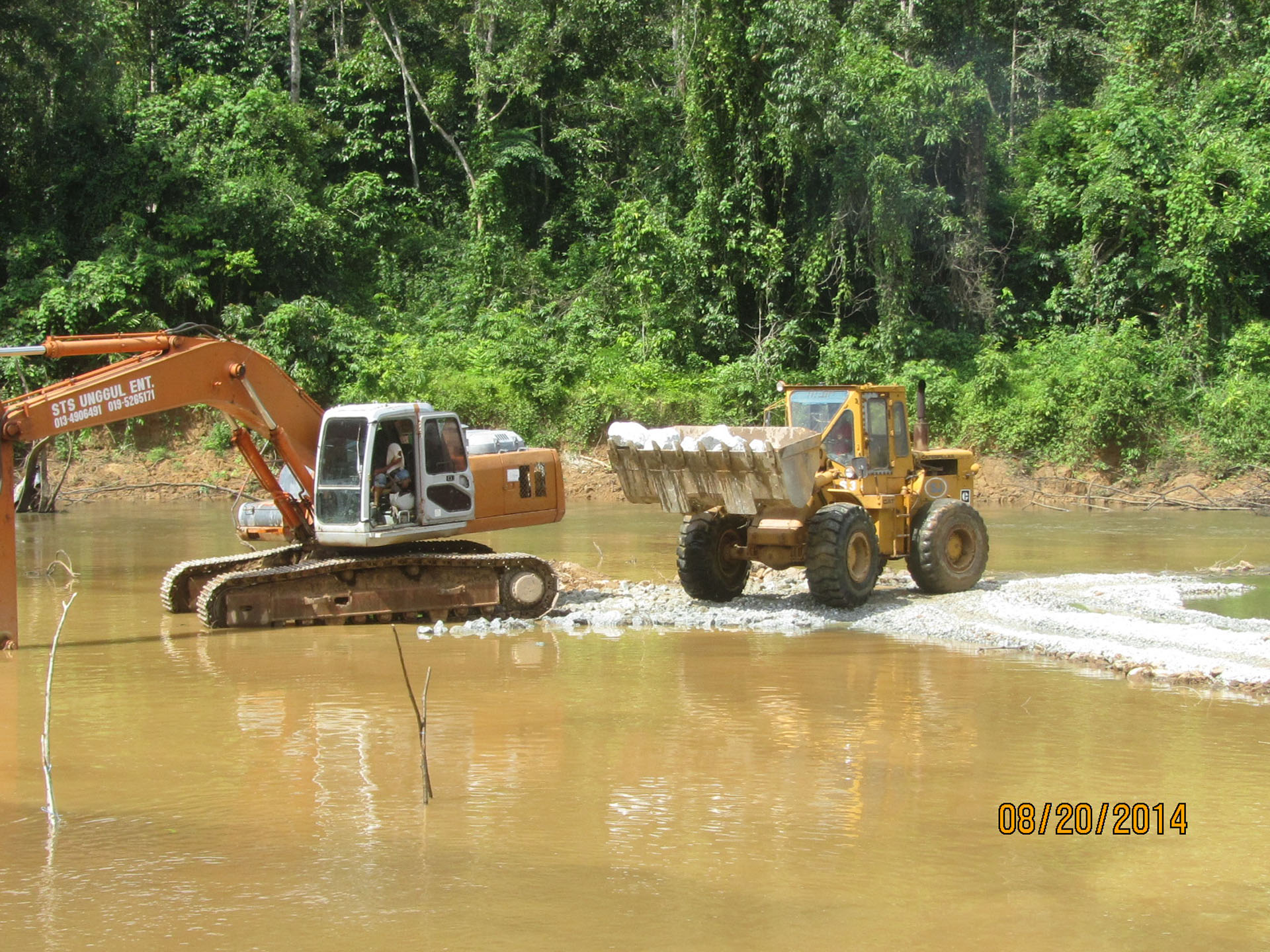
The restoration of lower Sulfur Creek required the use of heavy equip-ment for restoration. The idea that heavy equipment could be used in or near seasonally dry or flowing streams, by skilled operators and careful planning was a paradigm shift that was achieved by tactful communication, frequent demonstrations, and performance monitoring.  The fact that the Salmonid species returned was definitely beneficial.

One very important method (BMP) was developed and demonstrated for working in seasonally dry gravel-bedded streams, namely “Washing of Fines.”  Running heavy equip-ment in a stream channel during the dry season will ultimately bring the finer sand and silt particles to the surface.  These ‘fines” can cause water quality exceedance when the first winter storms come.

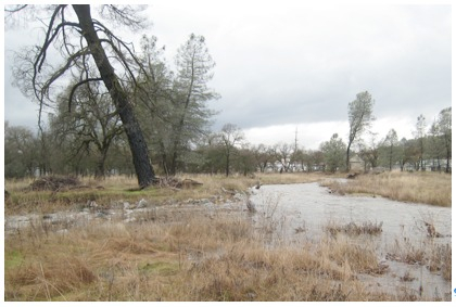
Figure 20.8 – Newbury Riffle on left diverts low flows to restored channel on right
6 years after project completion.

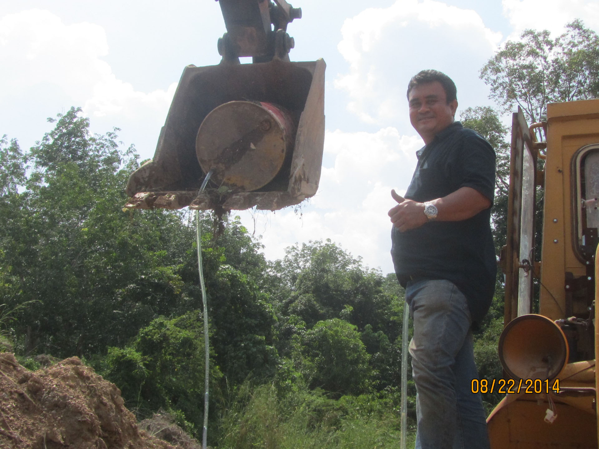
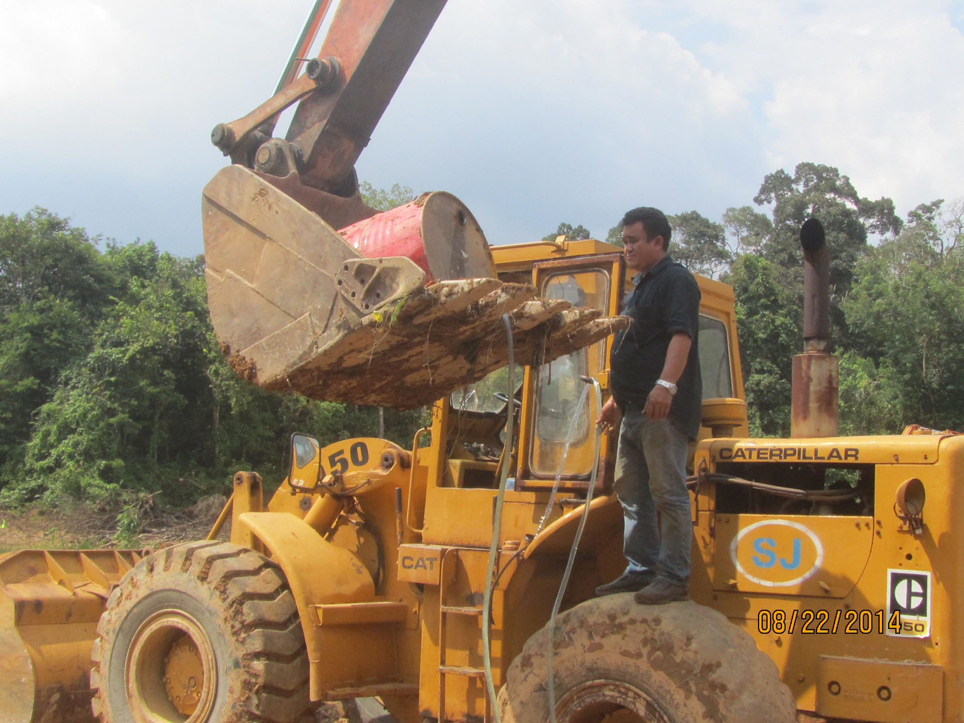
Washing fines is an “in-channel” sediment control method which uses water, either from a water truck or hydrant, to wash any stream fines, brought to the surface of the channel bed during restoration, back into the deep interstitial spaces of the gravel and cobbles, leaving clean cobble and gravel on the bed surface (see Figure 20.9).

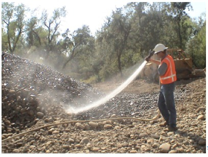
Fig. 20.9 – Washing fines using high pressure hose from a water truck.


SWAG monitored the stream turbidity during the first precipitation events resulting in stream flow.  The results were astonishing because the practice of “washing fines” most often resulted in reduced turbidity when comparing upstream and downstream values.  Sulphur Creek, being an urban stream with extensive upstream disturbances, could actually be “cleaned up” by Washing Fines in the restored construction reaches.


REFERENCES:

Maslin, P.E., W.R. McKinney, T.L. Moo (????). Intermittent Streams asRearing Habitat for Sacramento River Chinook Salmon,  Publication source????

NCHRP Report 544 – Environmentally Sensitive Channel and Bank Protection Methods, 2005, J. McCullah, D. Gray

E-SenSS – Environmentally Sensitive Streambank Stabilization Techniques, 2005, Salix Applied Earthcare, Redding, CA

For more projects like this, please visit www.springer.com to order our E-Book today! Want something to scribble notes in? Don’t worry – we have a hard cover available as well!
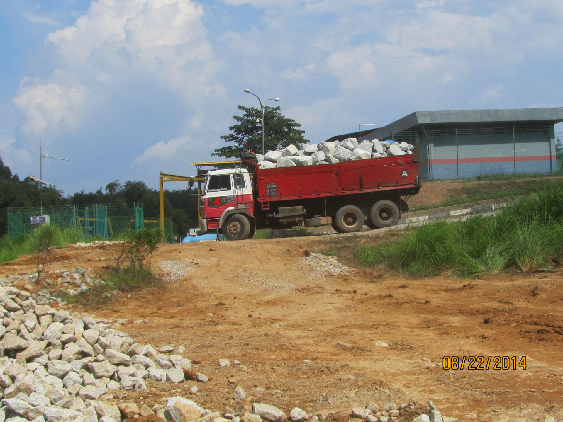
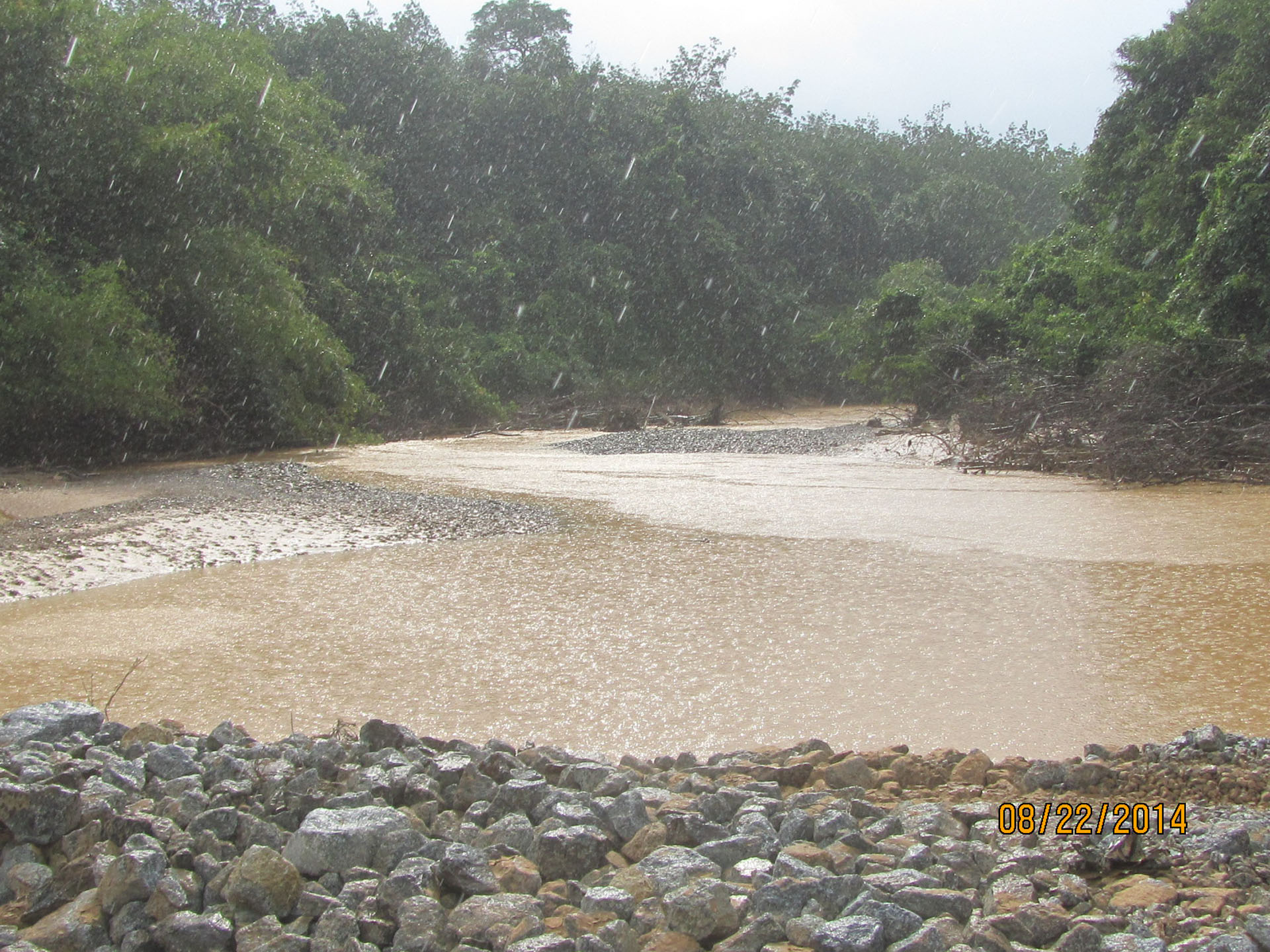
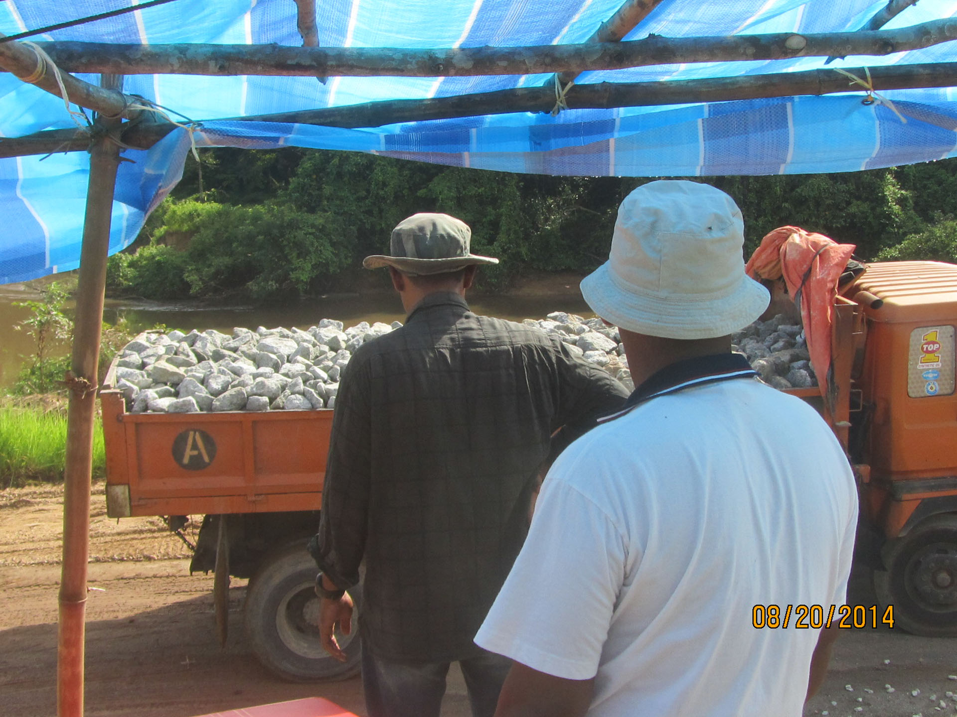
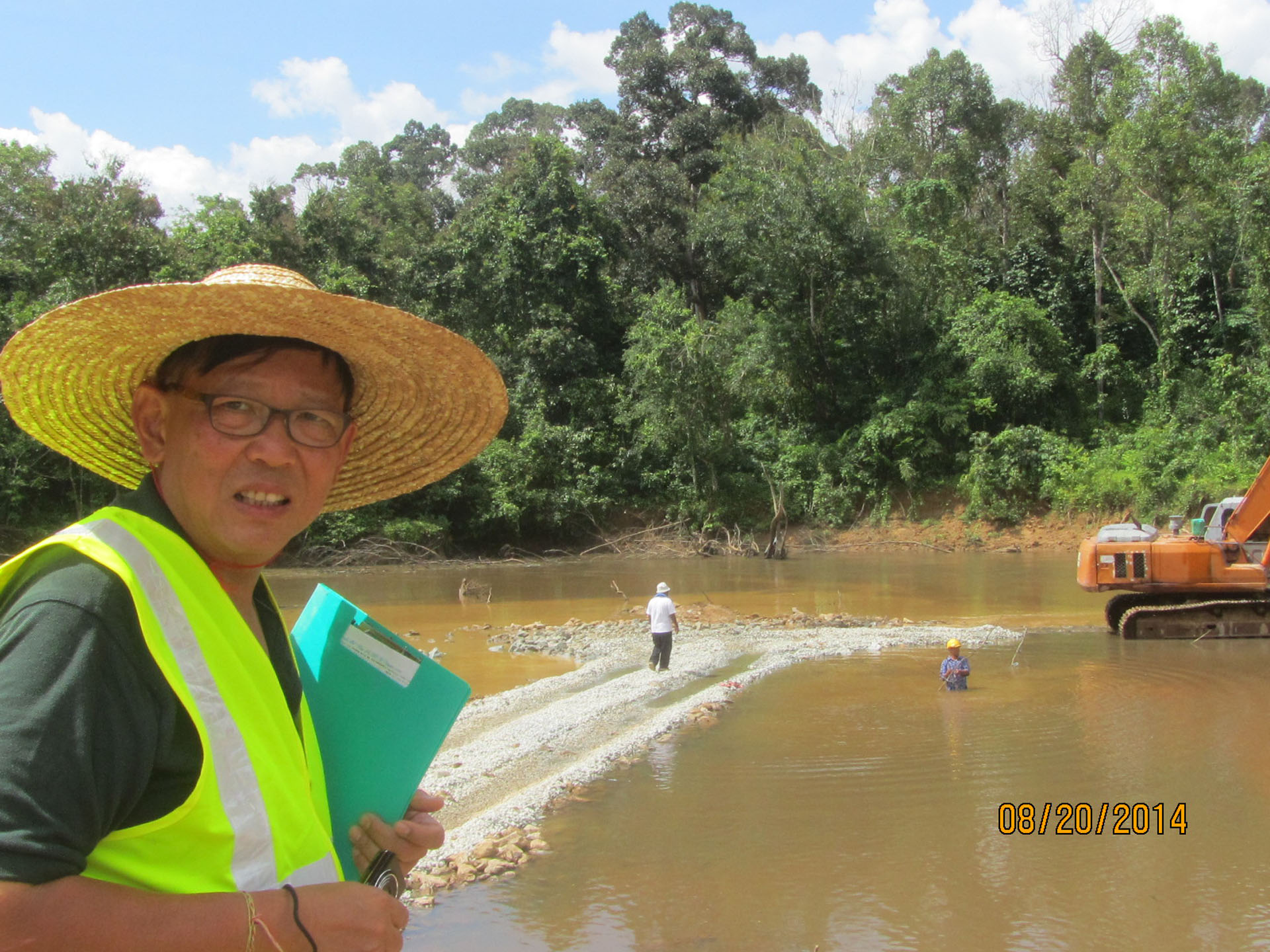
PROJECT TYPE:   Steep highway cutslope construction,revegetation field trials


 PROJECT SCALE:  MEDIUM

CLIENT/OWNER: Calif. Dept of Transportation

TECHNIQUES           

EMPLOYED:  Stepped Slopes, Compost / Soil Admixtures, Tree and shrub planting, Brushlayers, and Live staking (slope pinning)

GEOGRAPHIC LOCATION: Hwy. 299W, just below Buckhorn Summit, Shasta County, Calif.

GEOMORPHIC SETTING: Buckhorn Mountain is an exposed decomposed granite batholith, which separates Shasta and Trinity Counties in NW California.  Highway 299 W traverses Buckhorn Mountain for almost 15 miles over steep mountainous terrain, elevations of 1000 ft to 3000ft at the summit.  The Shasta Bally Batholith granitics have a high percentage of biotite and mica- type minerals that weather easily. Weathering is extensive because the batholith is deeply fractured, thus allowing the intrusion of water.

SITE CONDITIONS AND PROBLEMS: Hwy 299 is the main east/west route from Redding in the northern Central Valley to the Eureka in the North Coast, yet the terrain, erosivity, and environmental concerns make highway construction (straightening and widening) extremely challenging.  As of 2010 the CA Construction General Permit (in compliance with the Clean Water Act) became very stringent requiring all new construction to be “stabilized” before construction and permit coverage is considered “completed”.  Historically, steep cutslopes in these decomposed granites (DG) have been extremely difficult to vegetate and the bare reveling cutslopes can be a chronic source sediment.  The challenges to establishing vegetation are many –

The region can experience 50 inches of rain in the winter followed by six months of no precipitation at all and summer temperatures can often exceed 100 degrees for weeks on end.

Soil texture and composition are other impediments to stabilization. The decomposed granite parent material weathers rapidly to a sandy-silt textured soil that is extremely erosive. The soils derived from the Shasta Bally Batholith are within the Hydrologic Soil Group A, based on high permeability, and have been determined to be some of the most erosive in the nation.

On exposed cut slopes competent appearing bedrock quickly decomposes and ravels when exposed to moisture and freeze-thaw cycles. The soils resulting from these weathering processes are droughty. The water holding capacity and organic content are also very low, therefore these soils are difficult to re-vegetate.

These decomposed granite (DG) soils in upslope, undisturbed areas have extremely high infiltration rates and permeability. Therefore. the mountain has significant amounts of groundwater within. This presents another erosion mechanism that is especially problematic on steep highway cuts and fills, namely, exfiltration or “seepage erosion.” This often occurs when the slope face intercepts the groundwater table.

TREATMENT OBJECTIVES AND CONSIDERATIONS: The main goal was to test the viability of constructing a stepped highway cut and to conduct field trials for revegetation strategies.  Stepped slopes control erosion by breaking up the slope length – reducing the volume and velocity of stormwater runoff. It was hoped that the steps would also promote vegetative cover by providing a stable substrate while capturing and retaining loose soil and moisture.

Figure 1 – As-built plans for Post Mile 1.0 show curve correction and stepped slope project.


TREATMENTS SELECTED: 

  •  Stepped Slope:
  •  Back filling Steps:
  •  Willow Brushlayering:
  •  Landscape Treatments:  Several different treatments were tried and monitored including:
    • All the steps had native grass seeds, covered by straw mulch, planted on the horizontal surfaces.
    •  Native pine trees and shrubs were planted on the steps by drilling planting holes in the bench with power augers.
    •  Drip irrigation versus polymer (Dry Water).  The eastern half of the slope had the plants drip irrigated by gravity from a water tank installed at the top of the slope.
  • Live Willow Stakes /Slope Pins:  In late December and early January of the first winter the area experienced a snowstorm followed by a large rain event.  The upper center of the slope failed by a saturated slump.  The small landslide got caught on the mid-slope drainage bench but the saturated material threatened to initiate a larger failure.  In hopes of stabilizing the material until the summer when the slope could be re-constructed temporary measures were considered.  Plastic covers were rejected in favor Slope Pinning with live willow stakes.Live Willow Stakes, 30” to 36” long X ¾” diameter were driven into the slumping material at 3’OC.  The geotechnical principles of buttressing and arching were immediately manifested in stability of the mass and toe material.


Obstacles to Implementation:

There were no extraordinary obstacles.  There was a common false belief that mountainous, high elevations were not good locations for willow.  We had to point out that Salix sps. often play the role of pioneering species, coming into an area naturally after fires and landslides.  Then naturally-occurring plants in the general vicinity were discovered and pointed out.


Performance Evaluation: 

This stepped cut slope is currently well vegetated and has remained stable for 10 years, since the first winter failure which was stabilized permanently with willow stakes.  These techniques may prove to be the only feasible way to comply with the new California General Construction Permit.  The site has required little to no maintenance since the first winter.

BENEFITS AND LESSONS LEARNED:

Stepped slopes should be considered when steep, highly erosive cutslopes are difficult to stabilize.  The new Clean Water Act regulations will make it extremely difficult for Highway or County Road Department to construct slopes that are chronic sources of sedimentation.  Therefore these steep slopes with adverse soils will require extra engineering and earthwork techniques to ensure vegetation establishment.

Caltrans Division of Landscape Architecture conducted extensive research and developed Sustainable Erosion Control techniques for steep adverse soils.  Stepped Slopes, RECP Flaps, and RECP Wraps ,and Wire Mesh Confinement (VMSE) are a few engineering-approved techniques that have Standard Special Provisions.

Backfilling the steps resulted in less erosion and much better plant establishment.  Another important lesson learned was adding Certified Compost and Mycorrhizae to the steps and planting basins.  It was discovered that the steps could be cost-effectively constructed, then backfilled with compost/soil/mycorrhizae admixture as the slope was being built.  It was expensive to cut the benches then go back and fill in the steps.  Better to let the heavy equipment complete both tasks simultaneously.

The use of live stakes to buttress landslide material was also an important lesson.


REFERENCES

California Department of Transportation Landscape Architecture Program, Erosion Control Toolbox,  https://www.dot.ca.gov/hq/LandArch/ec/index.htm

***For More Case Studies like the one referenced above please check out our E-Book at www.springer.com for purchasing today! A great tool in visualizing which techniques work best for certain contiditons!***

Any other questions, please feel free to write us at – info@salixaec.com !


Thanks for reading –

The Dirt Time Team

That’s right! We’ve gone COMPLETELY HANDHELD and now offer our newly published book Bioengineering Case Studies: Sustainable Stream Bank and Slope Stabilization in E-Book format! (We still offer the 212 page book in hardcover as well for those of the older school fashion!)

Bioengineering Case Studies describes and evaluates 30 projects from across the United States where bio-stabilization was employed to address a detrimental naturally occurring process or byproduct of the built environment. Bio-stabilization (or soil bioengineering) refers to the use of plant materials, primarily live cuttings, arranged in the ground in different arrays to reinforce soils and protect upland slopes and/or stream banks against surficial erosion and shallow slope failures.

Examples included in the collection represent different regions of the country and their specific conditions and challenges. Each project is illustrated with a number of distinctive photographs to support the reader’s understanding and showcase the wide scope of projects and techniques presented. The volume is ideal for civil and environmental engineers and environmental scientists working on watershed, infrastructure projects, and municipal scale installations.

You are able to purchase the entire book, or just the few chapters that spark your interest! Get a sneak-peak into every chapter offered inside the book at www.springer.com. Not only is this great for lighter travel / in the field use, it let’s you purchase what you need!

Our contact us directly at info@salixaec.com for more details!!!

Thanks for reading!

– The Dirt Time Team

We haven’t heard much from John this past week, with him being busy exploring and working in Southeast Asia! But he has been able to send us some pictures which speak for themself! So if you’d like an update with what he’s been up to, check out the images below!


John should be returning back to the United States within the next few days and sharing more fun from his trip!

Thanks for reading!

– The Dirt Time Team

That’s right! John has flown half way across the globe to land right on the Malaysia / Thailand border! He has worked with the Malaysian Environment Department before in their country, as well as in ours! Earlier this year, John had taken about 20 of them on a 5-day bus tour around California and Nevada, showing them certain structural techniques – including Soil Stabilitation projects John has worked on! In years past, the group had met up with John McCullah at the Shasta College Erosion Control Training Facility to watch him in action! Below is a video from local KRCR News Channel Seven featuring the story!

Click here to watch video!

Can’t wait to share pictures from his trip once he returns!

Have a great work week!

– The Dirt Time Team

Select your currency
USD United States (US) dollar